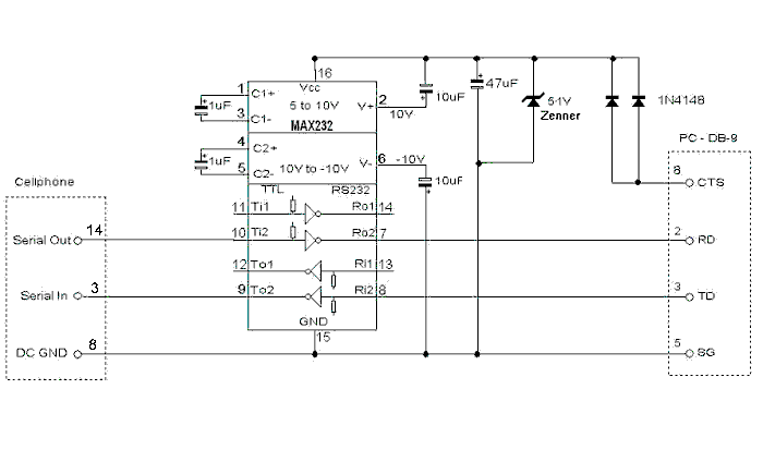
Cables, Interfaces and Pin-Outs
Alcatel HC600/800/1000 /OTE/OTC New!
Ericsson 2xx/3xx
Ericsson 6xx/7xx
Motorola
Nokia 1610, 2010, 2110, 3110, 8110
Nokia 5110, 6110
Panasonic
Philips
Sagem
Samsung
Siemens
If you have schematic or pin-out not listed here or you have more information email me.
Software to download "CICK HERE".
Alcatel HC600/800/1000
Alcatel HC600/800/1000 Pin-Out diagram
    1    3    5    7    9   11   13   15
    I    I    I    I    I    I    I    I
O                                        O 17
    I    I    I    I    I    I    I    I
    2    4    6    8   10   12   14   16


1 Vbat_ext               9 SDA_E
2 EMMI_PAE              10 GND
3 Mic                   11 GND
4 EMMI_OPE              12 DC_IN (charge)
5 GND                   13 Speaker
6 EXT_EMET              14 MARCHE
7 SCL_E                 15 DC_IN (charge)
8 EXT_RECDIT            16 GND
17 Antenna+internal switch (int/ext)
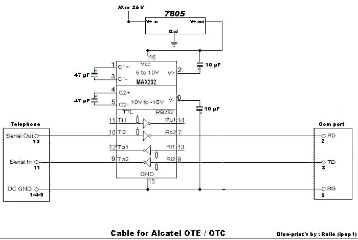
Alcatel OTE / OTC
Alcatel OTE /OTC Pin-Out diagram
    1    2    3    4    5   6   7   8  9  10  11  12  13  14


1-4-9    Gnd
11       Seial in
12       Serial out
PC Serial Port to Alcatel ote/otc Phone Interface
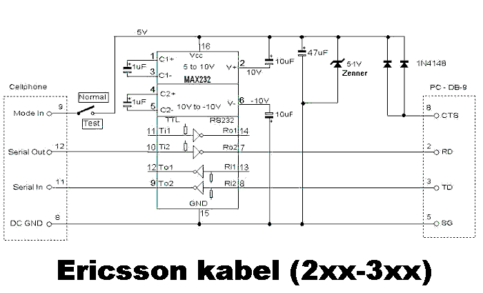
Ericsson 2xx/3xx
Ericsson 2xx/3xx Pin-Out diagram
1   In  Voice
2   In  +5V=External Power, 0V=Battery
3   Out Ext Speak control
4   Analog GND
5   Out Voice
6   Out +5V=POWER ON, 0V=POWER OFF
7   Out Charger control
8   Digital/DC GND
9   In  0V=normal,+5V=test, +12V=test+flash
10  In  Hook
11  In  TTL serial in
12  Out TTL serial out
13  In  0V for aprox 1 sec = POWER ON/OFF
14  In  DC Power supply
PC Serial Port to Ericsson 2xx/3xx Phone Interface
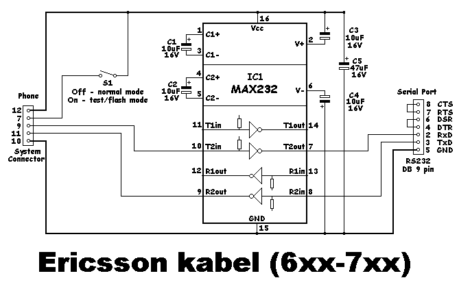
Ericsson 6xx/7xx
Ericsson 6xx/7xx Pin-Out diagram

Pin number is counted with keyboard up, from left to right
1: AFMS, Out, Audio from mobile station (external speaker, very small signal 10 mV).
2: ATMS, In, Audio to mobile station (external microphone).
3: EXTAUD, In, External Analog Audio Accessory Sense (enable external mic and speaker, connect to GND to do so).
4: GND, Audio Signal Ground, 0V reference
5: PORTHF, In, Portable Handsfree (Enable external mic and speaker, connect to GND to do so).
6: MUTE, Out, Music Mute (Digital output. High when calling. Could be off-hook signal).
7: VPPFLASH, In, Flash Memory Voltage and Service Voltage (Digital Input. Phone enters debug mode when tied to +5V at power-up).
8: VDD, Out, Logic Reference, Status ON (+5V out ? Sources over 100mA).
9: TFMS/DFMS, Out, Terminal Adaptor Equipment From Mobile Station/Data From Mobile Station (Serial output. Debug messages appear here at 112KBaud when in debug mode).
10: GND, Digital Ground and DC Return
11: TTMS/DTMS, In, Terminal Adaptor Equipment To Mobile Station/Data To Mobile Station (Serial input).
12: DCIO, In/Out, DC positive pole for phone battery charging and external accessory powering (Charger plus).
PC Serial Port to Ericsson 6xx/7xx Phone Interface
Motorola
Motorola 5200, 7200, 7500 Pin-Out diagram
Numbered right to left, keypad up, battery down looking from the bottom.
I assume *NO* responsibility
1) Gnd
2) Pos
3) True data (TD) (input)
4) Complimentary data (CD) (input)
5) Return data (RD) (output)
6) Audio gnd
7) Audio out
8) Audio in
Motorola 6200, 8200, 8400 Pin-Out diagram
Numbered left to right, keypad up, battery down
I assume *NO* responsibility
1) Audio Ground
2) V+
3) True data (TD) (input)
4) Downlink - Complimentary data (CD) (input)
5) Uplink - Return data (RD) (output)
6) GND
7) Audio Out - on/off
8) Audio In
9) Manual Test - ???
10) Battery Feedback
11) Antenna connector
Motorola StarTAC butt plug Pin-Out diagram
I assume *NO* responsibility
1) GND Connected with 22pf to pin 3
2) RF out
3) GND Connected with 33 pf to pin 8, 33 pf to pin 1, 33 pf to pin 7
4) BAT_FDBAK
5) MAN_TEST connected with 10k to L275
6) RS232_TX -  connected to MCU SPI bus
7) RS232_RX -  connected to MCU SPI bus
8) AUDIO_IN
9) AUDIO_OUT
10) GNDA (Ground reference) Connected with 33 pf to pin 13, 33 pf to pin 14
11) UPLINK    -|
12) DOWNLINK  -|- DSC bus connected to the BIC
13) DSC_EN_B  -|
14) EXT_B+
15) GND
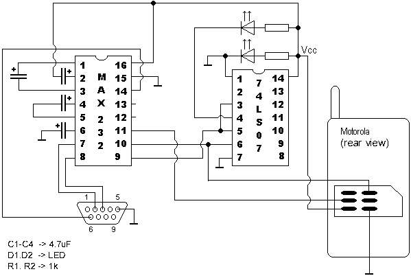
SIM Card Emulator Interface
Works with ASIM, medit, meditx, MotorolaHomeService, simemu.
Nokia 1610, 2010, 2110, 3110, 8110
Nokia 1610, 2010, 2110, 3110, 8110 Pin-Out diagram

1 GND - Charger/System Ground
2 V_OUT - Accessory Output Supply (Min/Typ/Max - 3.4 ... 10V Output Current 50 mA)
3 XMIC - External Microphone Input and Accessory Identification
Identification
TYP/MAX: 8... 50mV (The maximum value corresponds to 0dBm network level with input amplifier
gain set to 20 dB, typical value is maximum value -16dB)
ID Accessory Identification
* 1,7... 2,05V Headset adapter connected
* 1,15... 1,4V Compact hands free unit connected
* 2.22... 2,56V Infra red link connected
4 EXT_RF - External RF Control Input
Min/Max: 0... 0.5V External RF in use
Min/Max: 2.4... 3.2V Internal antenna in use
5 TX - FBUS Transmit
6 MBUS Serial Control Bus
* Logic low level: 0... 0.5V
* Logic high level: 2.4... 3.2V
7 BENA - Not Connected
8 SGND - Signal Ground
9 XEAR - External Speaker and Mute Control
* Min/Typ/Max: 0... 32... 500mV (Typical level corresponds to -16dBM)
Network level with Volume Control in Nominal Position 8dB Below Maximum
Maximum 0 dBM Maximum Volume Codec Gain -6dB)
Mute ON (HF SPEAKER MUTE): 0... 0,5V d.c.
Mute OFF (HF SPEAKER ACTIVE): 1,0... 1,7V d.c.
10 Hook - Hook Signal
Hook Off (Handset in use): 0... 0,5V
Hook On (Handset in use): 2,4... 3,2V
11 RX - FBUS Receive
* Accessory FBUS Receive Signal
12 V_IN - Charging Supply Voltage (Max 16V)
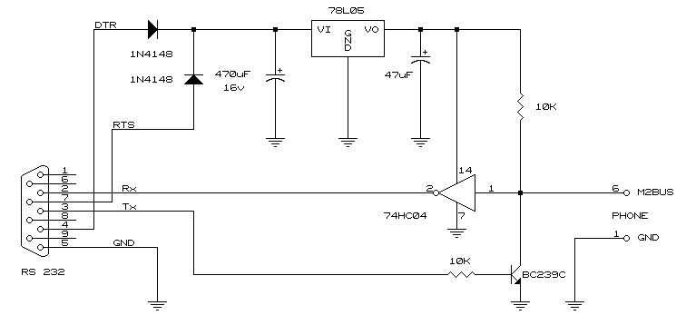
M2BUS Cable Schematic
This cable is the same for all Nokia phones.
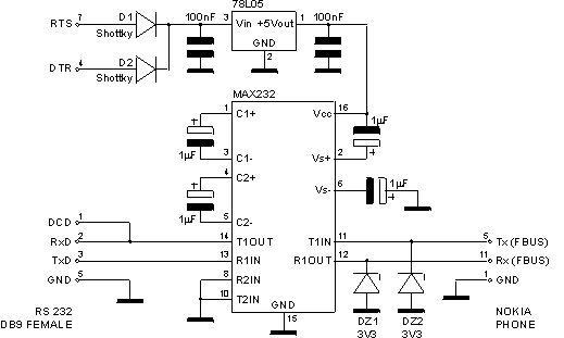
NCDS Interface Schematic for Nokia 3110, 8110, 8110i
Nokia 5110, 6110
Nokia 5110,6110 Pin-Out Diagram

1 V_IN - Charger Input Voltage 8.4V, 0.8A
2 CHRG CTRL - Charger Control PWM 32Khz
3 XMIC - MIC Input 60mV-1V
4 SGND - Signal Ground
5 XEAR - Ear Output 80mV-1V
6 MBUS 9600 B/s
7 FBUS_RX 9.6 - 230.4 KB/s
8 FBUS_TX 9.6 - 230.4 KB/s
9 L_GND - Charger/Logic Ground
M2BUS Cable Schematic
This cable is the same for all Nokia phones.

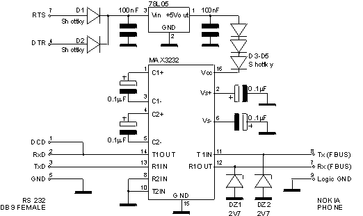
NCDS Interface Schematic for Nokia 5110, 6110
Panasonic
Panasonic G400,G450,G500,G520,G600 Pin-Out diagram
Panasonic G600 has different plug shape, however, pins are
numbered in the same way and they have the same signals.

            Up side of phone (keypad)

           16---------------9
  Ant        | | | | | | | |
             | | | | | | | |
            8---------------1
 1 Ground
 6 Serial up (in)
 7 Serial down (out)
13 Connect to 14
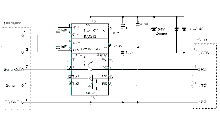
PC Serial Port to Panasonic G400,G450,G500,G520,G600 Phone Interface
Philips
Philips Fizz and Spark Pin-Out diagram
1   GROUND
2   GROUND
3   HANDS FREE ON/OFF
4   MUTE
5   TX
6   RX
7   RTS
8   REPROGRAMMING
9   ON HOOK CHARGER (APPROX 13V? TO 14V)
10  AUX MIC
11  AUX SPEAKER
12  GROUND
13  +VCC for Car Charger
14  +VCC for Car Charger
Sagem
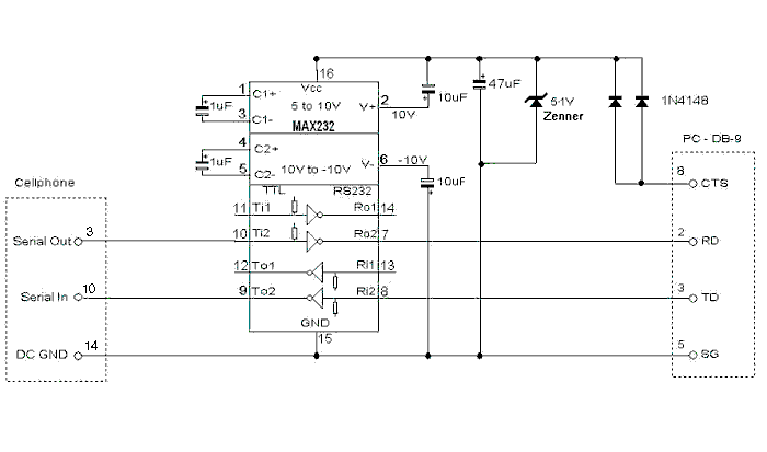
Sagem 612,615,715,725,730 Pin-Out diagram
        1      8
   []   --------
antenna --------
        9     16

3  - TX
10 - RX
14 - GND
PC Serial Port to Sagem 612,615,715,725,730 Phone Interface
Samsung
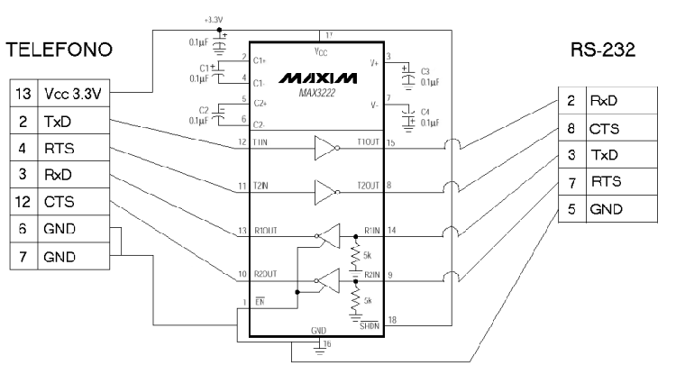
Samsung SGH600 Pin-Out diagram
I assume *NO* responsibility.
2  TxD
3  RxD
4  RTS
6  GND
7  GND
10 SCL
11 SDA
12 CTS
13 Vcc 3V
14 DCVolt
15 DCVolt
Samsung SGH600 Cable Schematic
Siemens
Simens S10,S11 Pin-Out diagram

3  Data In (Rx)
8  GND
14 Data Out (Tx)
Simens S10,S11 Cable Schematic
